CoronaArc Circuit Evolution
In 1996 we introduced the “CoronaArc” line of Igniters in anticipation of the market need for a high availability product capable of working at 2,000 deg. F. The “CoronaArc Circuit” is unique Patented Capacitor Discharge Ignition Circuit designed to deliver pulsating High Current Arcs to “burn” through contaminates and reliably deliver Ignition to Industrial Burners and Fuel Igniters.
Original PowerArc Circuit
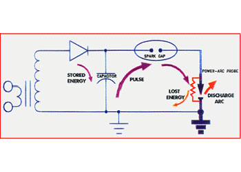
The accompanying schematic is a conceptual representation of our original PowerArc Circuit. Current from a 2,000 volt transformer is rectified and charges a storage capacitor. Next to this capacitor, on the output side, is a spark gap that is also referenced to ground potential by way of the semiconductor at the“Arc-Probe”. When the capacitor reaches 2,000 volts, the Spark Gap, being set at the voltage, breaks down and effectively becomes a closed switch. Once the Spark Gap is shunted, the full Amperage Potential of the capacitor is delivered to the Firing End of the “Arc Probe”. This is the Pulsed Arc that “burns through” contaminates.
NEW CoronaArc Circuit
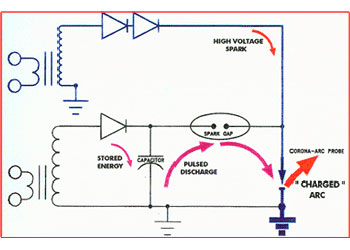
The Heart of the CoronaArc circuit is focused on the Firing End. The circuit is much the same as the PowerArc except the semiconductor material is eliminated. A second high voltage “transformer” and a supporting diode is added to create a continuous High Voltage DC Spark at the Firing End of the Igniter Electrode. The existence of this spark current at the Surface of the Igniter Electrode becomes the means by which the Spark Gap is referenced to ground potential and concurrently is the directed pathway by which the stored energy of the capacitor discharges a High Current Arc. In other words, we create a High Voltage spark at the firing end of the electrode, and the Capacitor part of the circuit pulsates a High Current Arc through it.
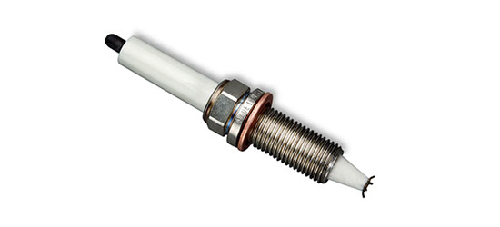
CoronaArc Spark Plug

The CoronaArc system eliminates the use of a SEMICONDUCTOR on the firing end; yet it delivers a superior pulsating High Current Non-Fouling Ignition Arc. As a result of this Semiconductor Free design, a whole new world of ignition potentials open up. Proprietarily produced at our facility, we maintain the flexibility to manufacture a variety of probe diameters and mounting configurations. We even have a few 500 psi models rated at Full Temperature Potential.
In Summary…
- Continuous High Temperature Exposure: 2,000 deg. F.
- More Power: No semi-conductor to absorb energy
- Reliability: Non semi-conductor “electric” seal to fail
- Unrivaled: Protruding fuel-grabbing electrode arrangement with superior alloys
- Flexible Design: Available in many sizes and mounting configurations
- Industrial Transformation: Low maintenance Non-Retract Ignition Potential.
Examples of High Temperature Applications
Two examples of how the CoronaArc increases reliability and saves on complexity, maintenance costs, and operational downtown:
MAIN BURNER
As seen in the illustration, the CoronaArc can be permanently placed in a high temperature radiant heat zone on Modern LowNox Burners and obtain reliable ignition. This is because there is combustible fuel swirling in front of the diffuser that is separate from the main fuel pattern and it is in a stagnation zone that facilitates flame propagation. The CornaArc Ignition Tip survives because it is not in direct contact with the main fuel spray. It sees the same radiant heat as the diffuser and it endures without needing retraction because it is made of similar materials.
FUEL IGNITER
Even on the most intense Fuel Igniters (such as used on Coal Burners), the CoronaArc Ignition electrode can be placed in direct contact with the fuel because the net temperature is still less than the probe’s 2,000 Oil Igniters, the “Spark” of the CoronaArc will reliably light them.
Live-for-Ever Arc Conduit
Our NEW patented circuit; solid state managed: now driving all our Ignition Exciters using a “live for ever” arc conduit.
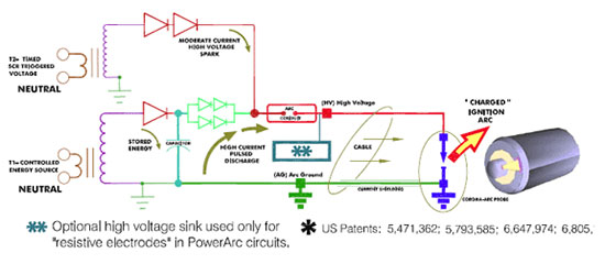
Circuit Description
A) Energy from T1 is rectified and charges the capacitor. It is held back from discharging because of the non conducting gap in the Arc Conduit and the Incongruent pathway of the T2 circuit.
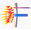
B) A moderate duration very high voltage spark from T2 is generated and pulses through the Arc Conduit and the surface of the surface of the CoronaArc Probe.
C) Because there is now a conductive current pathway across the Arc Conduit and the CoronaArc Probe, the electrons stored in the capacitor now have a pathway to discharge. And since this path is a relatively low resistance, the capacitor effectively sees a short circuit. For a few microseconds, the current becomes well over 300 amps and developes a short duration high intensity “hot” Arc. This is the energy that “burns” through contaminates and is intense enough to light the fuel that is on the surface of the Probe.
D) Energy form T2 is turned off. Because the current from T1 is naturally limited and/or is turned off, the stored energy of the capacitor becomes depleted and therefore the voltage drop across the Arc Conduit becomes small enough to cause it’s gap to cease to conduct.
E) At this point, T2’s energy goes back to being stored in the capacitor. The cycle repeats itself as in A.)